|
|||||||
| Jeep Friends Forum This is a forum for jeep friends to hang out. For more formal atmosphere hop over to the Technical Forum |
 |
|
|
Thread Tools | Rate Thread | Display Modes |
|
#1
 03-12-2003, 07:04 AM
|
|||
|
|||
|
Building a new crossmember, your opinions please.
I little background: 95 YJ, 4.0L. Auto, Atlas T-case. (Currie case, which means it can be "clocked" to flat).
I've got the Atlas installed to the factory trans adapter, and modified the sheetmatal floorboard to clear it (no body lift), and it is clocked to flat. I wish to install a seperate crossmember to hold the weight of the drivetrain, and a seperate aluminum skid plate. I plan on using (rubber) bushings on both sides of the frame for vibration absorbing, and spaning the crossmember between them. Then, bolting the crossmember directly to the bottom of the aluminum adapter. My question is, do you think that 1-1/4" square tube (7 gauge) is strong enough to support the weight of the drivetrain? I've thought about several different shapes of material for this and for clearance issues (front drive shaft and exhaust) the size mentioned above will be ideal for this. Opinions please. 
|
|
#2
03-12-2003, 07:33 AM
|
|||
|
|||
|
Re: Building a new crossmember, your opinions please.
Quote:
Were I to do it again, I would try something a little stiffer. Or, a different design. I get a tad bit more flex than I would prefer. I don't know how the square would compare. 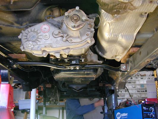
__________________
I am Savvy.
|
|
#3
03-12-2003, 08:08 AM
|
|||
|
|||
|
I've got a similar crossmember Chris but used 1 1/2 inch square 0.25 wall. This is on a fairly heavy drivetrain (NV4500 + Atlas) and have no flex to speak of so with your tranny weight I think the 7 gauge would be very adequate.
I'm curious, is the currie case just a standard Atlas with new clocking holes drilled or is it something beyond that?
|
|
#4
03-13-2003, 06:50 AM
|
|||
|
|||
|
Thanks for your input. I'm gonna build it. I had an idea and I think it will be stronger (less flex?) then 7 gauge.
I found a length of 11 gauge (.120w)(1-1/4") and a length of 11 gauge, 1" that will fit inside. I will laminate (slide) the two together and end up with the equivalent of 1/4" wall. I guess in my mind it just looks kinda wimpy compared to the factory's huge skidplate/crossmember, but since the new crossmember is only 28" in length, it will be plenty able to hold the few hundred pounds that the tail end of the drivetrain weighs. Art, Yes, the Currie case has the tapped holes that the clocking ring bolts to re-indexed in the aluminum case by about 20 degrees. I had my first Atlas case on the bench and was pondering how to get it to clock flat, when a buddy stopped by and asked me what I was doing. Ended up selling him that Atlas and ordered what I needed from A/A (along with 3.8 instead of 4.3, and I went with the 32 spline front output). Chris
|
|
#5
03-13-2003, 06:58 AM
|
|||
|
|||
|
Blaine,
Yes, that picture is worth a thousand words, thanks. Mine will be straight, however.
If I remember correctly from past posts, your skidplate is 5/16" aluminum? My aluminum supplier stocks 1/4" or 3/8" and when I was looking at the 3/8" it just looked overkill. Chris
|
|
#6
03-13-2003, 07:37 AM
|
|||
|
|||
|
Re: Blaine,
Quote:
It has some flex to it, and I would be more comfortable with 3/8" when I totally fubar this one. One thing I overlooked is that since it no longer has the brace holding it down, (motor and tranny weight) it has a tendency to get bowed upwards easier. The other plates do also, it's just the weight keeps them bowing downwards, or about level. Get the 3/8", you won't regret it.
__________________
I am Savvy.
|
|
#7
03-13-2003, 06:46 PM
|
|||
|
|||
|
Here is the completed unit:
 and the brackets:  I used TJ control arm rubber bushings mounted in 2.25" I.D.-DOM tubing for them. Seems to be strong and should still absorb vibration. I will use a piece of 3/8" thick aluminum for the skid plate. Thanks for your opinions. Chris.
|
|
#8
03-13-2003, 06:59 PM
|
|||
|
|||
|
Chris....thanks for the thread and the pics, etc. I am interested in seeing how this all turns out for you. Keep the input flowing!
|
|
#9
03-13-2003, 07:55 PM
|
|||
|
|||
|
Chris, my only concern is the shoulder effect at the edge of the continuous vertical weld on the frame. I would rather not see the weld get all the way to both edges.
Other than that, it looks great.
__________________
I am Savvy.
|
|
#10
03-13-2003, 08:43 PM
|
|||
|
|||
|
Quote:
|
|
#11
03-13-2003, 09:40 PM
|
|||
|
|||
|
Quote:
During flex of a member with a weld in or on it, any crack is most likely to develop at the edge or shoulder of the weld. If the weld traverses a member completely, it moves the potential for cracking to the edges where they start easier. Take a look at all the welds on your jeep frame. Pay attention to their orientation and how they went to pretty good lengths not to connect the edges of a structural member with any welding. Don't get me wrong, I am not saying it will crack, I would just be more comfortable if the weld were back from the top and bottom at least a half inch or so.
__________________
I am Savvy.
|
|
#12
03-13-2003, 10:32 PM
|
|||
|
|||
|
Well, I'll have to say I don't exactly understand the why of it and I guess I don't need to. I have noticed the factory welds are that way.
I just welded up the beginning of a cracked weld on my rear passenger upper control arm bracket. It was starting at the rear. Of course I welded it all the way down.  BTW I used my Ready Welder for the job as it had flux core wire in it. I was real proud of my welds! It felt so good to not have to take it some where. The little bity air grinder I bought for the Jeep worked great. Thanks, Ron
|
|
#13
03-14-2003, 06:42 AM
|
|||
|
|||
|
Quote:
How about if I added a gussett on the top edge, that spans the two tabs and extends past them on each side, with a slight bend downward, for say two inches or so? Would a gussett help distribute the stresses?
|
|
#14
03-14-2003, 10:47 AM
|
|||
|
|||
|
Ron,
How much was the Readywelder when you got it? I was at the bank the other day and a guy was asking me questions about my Jeep when the owner of Readywelder handed me a brochure. After I told him I already had one and how happy I was with it, the other guy became interested in it. The owner said that if you came down to the shop (in San Pedro), he'd let one go for about $350 (which is about what my dad paid for ours). Don't they normally sell for a hundred or two more? If so, that is something for people to consider who are interested in them. While he was there, I asked him a few more questions. He said if you use 1 battery and the stitch setting, it works great on sheetmetal.
__________________
Jeff
|
|
#15
03-14-2003, 11:22 AM
|
|||
|
|||
|
Jeff, I just bought one on Ebay for a little under $350( used. )There is a guy there who has 30 new ones. The starting bid is $435.00 I think.
Chis, can't wait to see the finished project! Looking great so far! Scott E.
__________________
Not only do I not know the answer... I don't even know what the question is
|
|
#16
03-14-2003, 12:12 PM
|
|||
|
|||
|
I got screwed and paid $500. I've been told there is one in a shop in town for $300 that's been sitting on the shelf for some time.
I really like it but $500 is insane for what it is. And then they give you those short cables......... If I break on the trail or want to weld big stuff it will be worth it. It sure is easy to use. I made a little doohicky that clicks on the wire feed setting. A must do.
|
|
#17
03-14-2003, 01:03 PM
|
|||
|
|||
|
Jeff, ping me at:
merlin57@mycingular.com I want one of those welders if I can get if for the $350 you are talking about. ChrisO - nice - you are going to have one fantastic YJ when you get it all put back together.
|
|
#18
03-14-2003, 01:23 PM
|
|||
|
|||
|
Sent you a message Robert. Ron, $500 still isn't a bad price when you compare the price to the Premier Power Welder. I'm not a knowledgeable welder by any means, but those who are who have seen it says it does a nice job. It sure beats having to stick weld which looks really tough.
Have you tried 3 batteries? The guy said you'd probably never need the power but it'll do some heavy stuff. I would recommend at least a 20' extension cable. They roll up to about a 6" diameter and really make it a lot easier to weld. We have two 20' footers and occasionally use them.
__________________
Jeff
|
|
#19
03-14-2003, 02:03 PM
|
|||
|
|||
|
No, just two but it seems plenty powerfull! I think I'd need bigger wire than .035 for three batteries. I think the next size is .045. I can't imagine me doing much of that.
Robert. You will really like it and it seems simple. They say the straight dc from batteries is smoother than converted power, and though I'm a beginner, it does seem easier. Kind of a no brainer. Just fool with the wire speed until you get the desired results. 
|
|
#20
03-14-2003, 02:14 PM
|
|||
|
|||
|
Ron,
Could you post some pics of the wire you put to retain the wire speed adjustment? I just got it where I liked it and put a piece of tape over it so I wouldn't accidentally move it with my thumb.
__________________
Jeff
|
|
#21
03-14-2003, 02:36 PM
|
|||
|
|||
|
Quote:
Do you get the extension cables thru RW. Or did you make your own? From what I have read with 3 battery's and .045 wire it will weld 1/2 inch single pass  Now that is amazing if true. Now that is amazing if true.Scott E.
__________________
Not only do I not know the answer... I don't even know what the question is
|
|
#22
03-14-2003, 02:39 PM
|
|||
|
|||
|
Quote:
__________________
I am Savvy.
|
|
#23
03-14-2003, 03:12 PM
|
|||
|
|||
|
Ah so, mrblaine! After reading your discussion with Chris the light came on. So, just welding a small bracket, say, in the middle of the frame, You can weld from one end of the bracket to the other?
|
|
#24
03-14-2003, 03:16 PM
|
|||
|
|||
|
Quote:
 I drilled a small hole in a safe place right next to the dial and bent a small piece of spring steel to click on the dial (notice the knob has a serated surface just made for something like this?) and screwed it in. After giving a bit of thought, probably a clip of a pen or something would work just as well.
|
|
#25
03-14-2003, 03:38 PM
|
|||
|
|||
|
Quote:
__________________
Jeff
|
|
#26
03-14-2003, 04:02 PM
|
|||
|
|||
|
Quote:
Very commonly found on the ends of tow truck jumper cables with corresponding plug at either end of the tow rig. Just plug and jump. I think they are good up to 1/0 wire which is sort of weird as that size cable generally handles more than 175 amps. I have also seen them at race car shops and sites and last saw them at TMR in Orange. Del City wire and cable also carries them. If you do use them, make sure that you get the bushings for the size wire you plan on using. The pins come generally sized for the 1/0 and adapt downwards for the smaller cable. I generally stock the bushings for #4 as that is the common size on the ambulance jumper cable sets I built. I found a link- http://www.andersonpower.com/products/mp/sb.html The yellow connector in the SB series is what we use, only in red. Be careful, they are color coded and only like colors will plug into themselves.
__________________
I am Savvy.
|
|
#27
03-14-2003, 04:29 PM
|
|||
|
|||
|
Yeah, those look to be the ones. I'll take a look at the extension cables and see what it says on the plugs and what size wire it uses in case anybody wants to make their own.
__________________
Jeff
|
|
#28
03-14-2003, 05:31 PM
|
|||
|
|||
|
Thanks guy's
Scott E.
__________________
Not only do I not know the answer... I don't even know what the question is
|
|
#29
03-14-2003, 05:51 PM
|
|||
|
|||
|
Quote:
Would you feel safe drilling a hole all the way through your frame about an inch and a half in diameter if you started your pilot about a quarter of an inch away from the edge? That would leave a big chunk missing from one of the box sides of the frame. I don't think any of us would be comfortable with it, yet we are quite happy with the same size hole in the middle of the box section in the rear section of our frames.
__________________
I am Savvy.
|
|
#30
03-14-2003, 06:17 PM
|
|||
|
|||
|
Quote:
Well said! I do like the long gussett idea and that is what I'm gonna do. If I would have not had a brain-fart I would have known the fact that you pointed out. I have seen the way the factory welds brackets on the frame (ie: body mount outriggers) and they don't weld all the way. I shoulda been more observant (and studied your picture closer) before I went gung-ho with my brackets. Thanks for your input.
|
|
| Bookmarks |
|
|
 Similar Threads
|
||||
| Thread | Thread Starter | Forum | Replies | Last Post |
| Venting about my Job.... | Wind_Danzer | Jeep Friends Forum | 16 | 07-19-2005 10:15 PM |
| My little idea of a home brewed crossmember for the tranny....any good? | LeadFoot | Technical Forum | 6 | 03-18-2005 09:15 AM |
| Should I change my RE crossmember from the 3 piece to the 5 piece? | TJeeper | Technical Forum | 1 | 12-02-2004 04:33 PM |
| RE crossmember swap question | Darrell C | Technical Forum | 1 | 10-15-2004 08:20 AM |
| Anyone build a crossmember for the tcase/tranny? | Brad Kilby | Jeep Friends Forum | 16 | 09-18-2001 09:47 PM |


 Linear Mode

